A layered SCADA architecture in practice
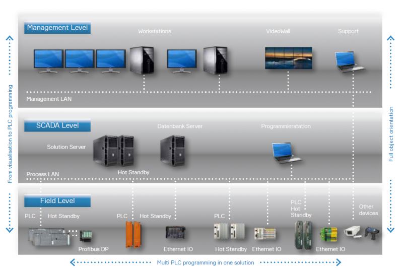
This diagram shows a three level industrial automation architecture consisting of a management level, a SCADA level, and a field level. I worked with this type of system for eight years on public infrastructure projects such as tunnels, bridges, pump stations, and hydraulic installations.
The diagram is accurate in structure, but it hides the real complexity. In reality this is not a static system. It is continuously running, evolving, being extended, patched, and verified while remaining operational.
Management level
The management level contains operator workstations, video walls, and support systems connected to a separate management network. This is where operators monitor the process and respond to alarms and incidents.
From an engineering perspective, the main concern at this level is usability under stress. During incidents, operators must be able to understand the situation immediately. Screen layout, alarm philosophy, and response times matter more than visual design. Any ambiguity here directly affects safety and availability.
Network separation is also essential. The management LAN must not interfere with real time process communication.
SCADA level
The SCADA level forms the logical core of the system. It typically consists of redundant SCADA servers, a database server, and one or more engineering stations. Hot standby configurations are common and necessary.
In practice, redundancy is not just a checkbox. Failover behavior must be tested regularly. Data consistency, alarm continuity, and client reconnection behavior are all failure modes that need verification. I have seen systems where redundancy existed on paper but failed during real incidents due to untested assumptions.
Engineering stations at this level are powerful and dangerous at the same time. Changes propagate quickly through the system. That is why access control, change management, and clear versioning are critical.
Field level
The field level consists of PLCs, distributed IO, and communication networks such as Profibus and Industrial Ethernet. This is where control logic interacts with the physical process.
Here, determinism and predictability are key. PLC programs must behave exactly the same every cycle. Timing, interlocks, and failure handling must be explicit. Many systems use hot standby PLCs to eliminate single points of failure, but this introduces additional complexity in synchronization and diagnostics.
What is often underestimated is the long lifetime of this layer. PLC hardware and field wiring may remain in service for twenty to thirty years. Software decisions made early will affect maintainability for decades.
Why this architecture works
This layered structure enforces separation of responsibilities. Visualization does not control hardware directly. Control logic does not depend on operator screens. Network traffic is segmented by function.
During my work, this separation proved essential for troubleshooting and verification. When something fails, you need to know where to look. A flat architecture would be unmanageable at this scale.
Engineering lessons
Working with this system for eight years reinforced a few principles that I still apply today.
Design for failure, not for normal operation.
Verify behavior instead of trusting diagrams.
Document decisions so they remain understandable years later.
Keep systems boring and predictable.
This diagram may look traditional, but the engineering thinking behind it remains relevant far beyond industrial automation.